The LDR light sensor module is capable of detecting and measuring light in the surrounding environment. The module provides two outputs: a digital output (LOW/HIGH) and an analog output.
In this tutorial, we will learn how to use an Arduino and an LDR light sensor module to detect and measure the light level. Specifically, we will cover the following:
How to connect the LDR light sensor module to an Arduino.
How to program the Arduino to detect light by reading the digital signal from the LDR light sensor module.
How to program the Arduino to measure the light level by reading the analog signal from the LDR light sensor module.

image source: diyables.io
Afterward, you can modify the code to activate an LED or a light bulb (via a relay) when it detects light.
If you prefer a light sensor in its raw form, I suggest exploring the tutorial on the Arduino - Light Sensor.
Hardware Required
Or you can buy the following sensor kits:
| 1 | × | DIYables Sensor Kit (30 sensors/displays) | |
| 1 | × | DIYables Sensor Kit (18 sensors/displays) |
Please note: These are Amazon affiliate links. If you buy the components through these links, We will get a commission at no extra cost to you. We appreciate it.
About LDR Light Sensor Module
The LDR light sensor module can be utilized to detect the presence of light or measure the light level in the surrounding environment. It provides two options via a digital output pin and analog output pin.
Pinout
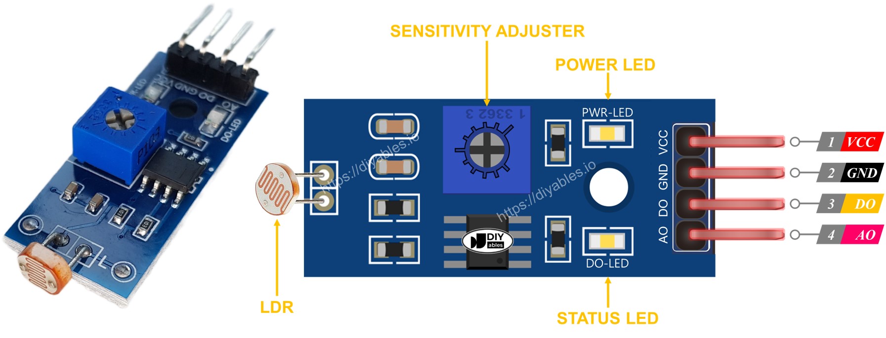
The LDR light sensor module includes four pins:
VCC pin: It needs to be connected to VCC (3.3V to 5V).
GND pin: It needs to be connected to GND (0V).
DO pin: It is a digital output pin. It is HIGH if it is dark and LOW if it is light. The threshold value between darkness and lightness can be adjusted using a built-in potentiometer.
AO pin: It is an analog output pin. The output value decreases as the light gets brighter, and it increases as the light gets darker.

image source: diyables.io
Furthermore, it has two LED indicators:
One PWR-LED indicator for power.
One DO-LED indicator for the light state on the DO pin: it is on when light is present and off when it is dark.
How It Works
For the DO pin:
The module has a built-in potentiometer for setting the light threshold (sensitivity).
When the light intensity in the surrounding environment is above the threshold value (light), the output pin of the sensor is LOW, and the DO-LED is on.
When the light intensity in the surrounding environment is below the threshold value (dark), the output pin of the sensor is HIGH, and the DO-LED is off.
For the AO pin:
The higher the light intensity in the surrounding environment (light), the lower the value read from the AO pin.
The lower the light intensity in the surrounding environment (dark), the higher the value read from the AO pin.
Note that the potentiometer does not affect the value on the AO pin.
Wiring Diagram
Since the light sensor module has two outputs, you can choose to use one or both of them, depending on what you need.
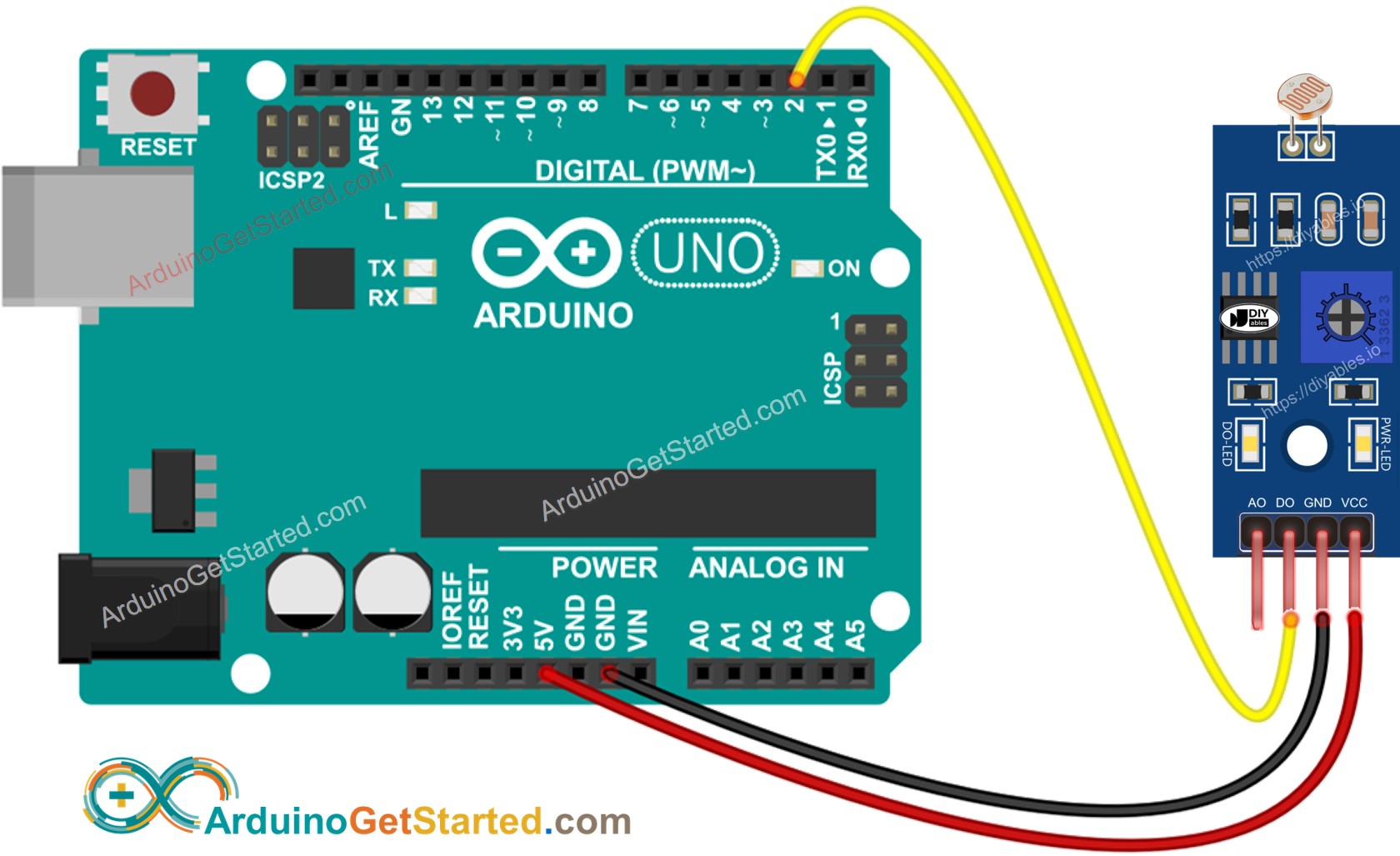
The wiring diagram between Arduino and the LDR light sensor module when using DO only.

This image is created using Fritzing. Click to enlarge image
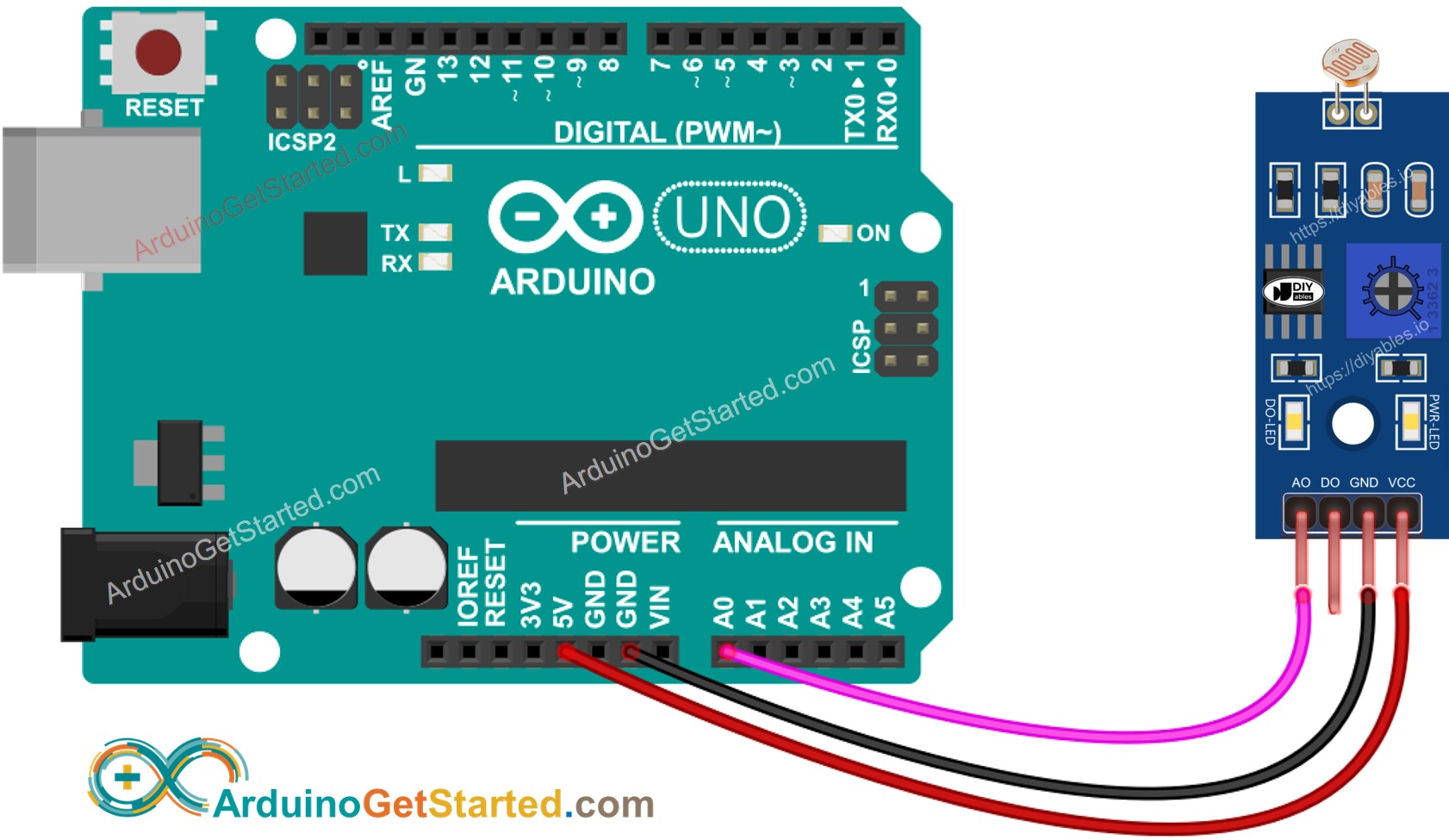
The wiring diagram between Arduino and the LDR light sensor module when using AO only.

This image is created using Fritzing. Click to enlarge image
The wiring diagram between Arduino and the LDR light sensor module when using both AO an DO.

This image is created using Fritzing. Click to enlarge image
The real wiring:

Arduino Code - Read value from DO pin
/* * Created by ArduinoGetStarted.com * * This example code is in the public domain * * Tutorial page: https://arduinogetstarted.com/tutorials/arduino-ldr-module */#define DO_PIN 2 // Arduino's pin connected to DO pin of the ldr modulevoid setup() { // initialize serial communication Serial.begin(9600); // initialize the Arduino's pin as an input pinMode(DO_PIN, INPUT);}void loop() { int lightState = digitalRead(DO_PIN); if (lightState == HIGH) Serial.println("The light is NOT present"); else Serial.println("The light is present");}
Quick Steps
Copy the above code and open with Arduino IDE
Click Upload button on Arduino IDE to upload code to Arduino
Cover and uncover the LDR light sensor module by your hand or something
See the result on Serial Monitor.
COM6
Send
The light is presentThe light is presentThe light is NOT presentThe light is NOT presentThe light is NOT presentThe light is presentThe light is presentThe light is present
AutoscrollShow timestamp
Clear output
9600 baud
Newline
Please keep in mind that if you notice the LED status remaining on constantly or off even when there is light, you can adjust the potentiometer to fine-tune the light sensitivity of the sensor.
Now we can customize the code to activate an LED or a light when the light is detected, or even make a servo motor rotate. You can find more information and step-by-step instructions in the tutorials provided at the end of this tutorial.
Arduino Code - Read value from AO pin
/* * Created by ArduinoGetStarted.com * * This example code is in the public domain * * Tutorial page: https://arduinogetstarted.com/tutorials/arduino-ldr-module */#define AO_PIN A0 // Arduino's pin connected to AO pin of the ldr modulevoid setup() { // initialize serial communication Serial.begin(9600);}void loop() { int lightValue = analogRead(AO_PIN); Serial.println(lightValue);}
Quick Steps
Copy the above code and open with Arduino IDE
Click Upload button on Arduino IDE to upload code to Arduino
Cover and uncover the LDR light sensor module by your hand or something
See the result on Serial Monitor.
COM6
Send
1451461465726789459561001100210121013645546346172
AutoscrollShow timestamp
Clear output
9600 baud
Newline
Video Tutorial
We are considering to make the video tutorials. If you think the video tutorials are essential, please subscribe to our YouTube channel to give us motivation for making the videos.
Function References
pinMode()
digitalRead()
analogRead()
Serial
The Best Arduino Starter Kit
See the best Arduino kit for beginner
See Also
Arduino - Light Sensor
Arduino - Light Sensor Triggers LED
Arduino - Light Sensor Triggers Relay
Arduino - Light Sensor Triggers Servo Motor
※ OUR MESSAGES
We are AVAILABLE for HIRE. See how to hire us to build your project
If this tutorial is useful for you, please give us motivation to make more tutorials.
You can share the link of this tutorial anywhere. Howerver, please do not copy the content to share on other websites. We took a lot of time and effort to create the content of this tutorial, please respect our work!
PREVIOUS
NEXT
DISCLOSURE
ArduinoGetStarted.com is a participant in the Amazon Services LLC Associates Program, an affiliate advertising program designed to provide a means for sites to earn advertising fees by advertising and linking to Amazon.com, Amazon.it, Amazon.fr, Amazon.co.uk, Amazon.ca, Amazon.de, Amazon.es, Amazon.nl, Amazon.pl and Amazon.se
Copyright © 2018 - 2024 ArduinoGetStarted.com. All rights reserved.
Terms and Conditions | Privacy Policy
Email: ArduinoGetStarted@gmail.com
